Anti-tank ditch at Crowborough
Posted: 13 February 2010 23:08
In a previous post I mentioned a series of visits to part of the GHQ Line at Old Lodge Warren. New documentary research and fieldwork have revealed some interesting aspects of an anti-tank ditch in the area.
Location in the landscape

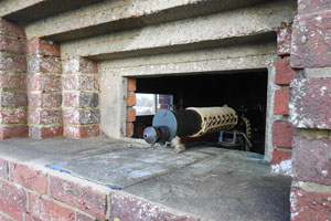
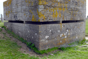
The stretch of ditch I'll be describing is in the area of Pillbox A107, which is a variant type peculiar to this area of the Weald.
The ditch serves to bypass shallow meanders in a stream that offer less resistance to tanks; the image at right shows the general layout.
The ditch is highlighted in yellow, the stream in blue and the railway line in red.
The pink spots are pillboxes; A107 is our variant type dug in to embrasure level while A108 is a Type 24 pillbox.
The southern end of the anti-tank ditch follows a course along 340° for just over 200m before turning on 30° for another 100m; at this point it rejoins the natural stream just south of the sewage works that are just visible at the top of the map image.
Cutting the new ditch probably saved time in trying to dredge the existing stream and also shortened the anti-tank line, economising in pillboxes and providing them with nice straight lines along which to shoot.
The photo below shows the general nature of the bypassed stream.

This section is shallow enough to be forded on foot (you can see the stream bed in the photo), and although banked on both sides is actually too wide in places to prevent a tank from being able to negotiate each bank as a separate obstacle.
Had the stream been narrower, a tank would not be able to almost sit flat on the stream bed before attempting to mount the far bank, but as neither bank is nowhere near high enough in most places to hinder tracked vehicles, this is of little consequence.
Dredging the stream was probably not an option due to the relatively fast flow of water causing movement of sediment that would eventually undo the work. Full access to the stream by the machinery needed to dredge was probably hindered too, making a fresh cut by far the easiest option.
The photo below shows the nature of the ditch as it survives today; although overgrown and with trees growing in it, the general shape is very much evident. This represents perhaps the best preserved section. In some places the ditch has been backfilled to provide crossing points for cattle/vehicles and some sections are much shallower after 70 years. General dimensions are about 5.5m wide at the top, 1.8m wide at the bottom and about 2m deep, although silting up and water in the ditch may affect the latter two dimensions.

Ditch design
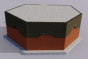
A series of visits to take measurements of some sections and compare the ditch with textbook examples resulted in my building the Google Sketchup model seen below.


A quick description of the ditch is required. According to the relevant pamphlet of Field Engineering (All Arms) 1940, excavator equipment removes the spoil from the ditch, making the bank facing the enemy as vertical as the ground will allow. The spoil could be placed on either or both banks to enhance the effectiveness of the obstacle.
The near vertical face would require revetment, and although various methods were approved, the one we're interested in here is the use of wooden pickets to hold a layer of brushwood in place on the face of the bank. These revetment pickets were ideally to be 6-8 inches in diameter and were hammered down into the floor of the ditch.
Set back from the ditch was an anchor picket which would be used to retain the revetment in place by the use of 4-8 strands of wire windlassed to provide strength by entwining the strands. Each revetment picket would have its own wire and anchor, but the latter were not to all be placed at the same distance from the ditch in case they created a line of cleavage in the bank that could cause a collapse. Anchors were to be below ground level to protect them from breakage by vehicles. The spoil could be built up at the tops of the pickets which were interlaced with more brushwood.
The surviving evidence
Although I was hoping to find some evidence, the presence of a few rotten revetment pickets was a pleasant surprise. One picket is indicated by each red line in the photo below. The spacing would appear to have been about 90cm, which ties in with the official guidelines.
Three pickets have sheared off at the base, but we have one that still stands at a rough angle of 80° which would indicate that the revetted wall was almost vertical. We do have an anomaly though; the angle of the earth bank (and the broken pickets) is about 48° and pretty much consistent along the entire length. It may be that the resultant void was completely filled with brushwood (as illustrated in the cross-section above) as the bank is unlikely to have been cut back at a shallower angle postwar in a way that left the pickets in situ. Wholesale landslip of the face of the bank into the ditch also appears unlikely, leaving this question unresolved as yet, but we shall come back to this later on.

The presence of four or five strands of wire used to connect the picket to its anchor is also apparent on most of the surviving pickets. It would appear that these wires were deliberately cut after the war. Once the brushwood revetment had rotted away it would have left the wires spanning the void between vertical picket and sloping bank, so they might have been cut for safety purposes.
The photo below shows one picket that still stands nearly vertical; it has 70cm of wire still looped around it, hanging down. Lifting the wire and setting it horizontal brought it into contact with the edge of the bank as seen in the photo, leading me to believe that somebody had walked along the top of the ditch cutting the wires. This was reinforced by a neighbouring picket with a similar length of cut wire still attached. In another section of the ditch the wire lengths still attached were all about 20cm, perhaps indicating their being cut by somebody actually standing in the ditch rather than on the bank in this particular stretch. All cases of surviving wire showed that all the individual strands were cut at roughly the same length, indicating that they had been severed together in one or two slices with the wire-cutters.

One thing we can speculate on concerning the process of revetment is use of a technique described in the manual. To avoid having to cut trenches through the spoil heap to install the anchor pickets and wires, a time-saving trick would be to position the anchors and wires before the ditch was excavated and the spoil dumped on the bank. A small picket was placed on the ditch line to keep the wire in place; digging would subsequently dislodge this 'surrogate' picket, whereupon the wire could then be slipped over the real revetment picket once it had been sunk in position.

The reason I wonder if this was done at Crowborough is that all the revetment stakes I measured were about 9cm in diameter (smaller than recommended by the manual), whereas the internal diameter of the wire loops is about 10cm (photo right).
This may indicate that the loops were fixed in size to deliberately be slightly larger to facilitate their being slipped over the ends of the pickets rather than having been windlassed tightly around them. The pickets have been rotting over the years and may have shrunk as a result, but the eight examples of surviving wire loops examined are of uniform shape and size.
The fact that the ditch has otherwise survived so well without revetment is remarkable.
The images below are of the Sketchup model; note how pillbox A107 is situated on the bend in the ditch and can cover along both stretches.

I should point out that I constructed this model based on fieldwork and the military textbook. However, since building the model and generating these images I have finally acquired a copy of an important article entitled The construction of the GHQ stop-line: Eridge to Newhaven, June-November 1940 (Fortress issue 16, 1993) written by I.D. Greeves, the Civil Engineer who helped oversee the construction of the defences. Included in this fantastic first-hand account are photographs of some stretches of anti-tank ditch, and I'm pleased to say that my interpretation is not too different from the recorded appearance. The photographs show revetment pickets of varying sizes and lengths (mine are uniform because the same one is reused throughout the model) and in reality, the revetment is nowhere as neat and tidy as the model suggests, but otherwise I'm happy with it. In fact, the three published photographs show different stretches of ditch and their appearance differs between all of them.

Documentary Evidence
I mentioned at the top that I had undertaken some new documentary research. Greeves makes reference to the movement of earth-moving equipment from Staines Reservoir to the Newhaven-Eridge area by a civilian contractor. However, some interesting information from the war diary of a Royal Engineers excavator company indicates that they had machinery working on the ditches in the Crowborough area:
Day 1: Instructed to form No.2 Section and commence work at Crowborough, Sussex. 11 Other Ranks proceeded as advance party.Day 2: 40 ORs proceeded to Crowborough and commenced work on G.H.Q. Stop Line (A/tk ditch). Plant in use: 7 draglines, 1 shovel.
Day 26: Half No.2 Section completed task and moved to Essex.
Note: the above text is not verbatim.
The Engineer unit in question found themselves working elsewhere in East Sussex in subsequent months, including Newhaven and Rye.
So why is this information of interest other than to provide unsurprising evidence of military excavators working on the GHQ Line? The most important aspect is the list of plant in use. (The original diary extract lists the specific types of plant as well as some other machinery I've not included above).
The manual (image below) states that the near vertical face of the ditch is best cut by a dragshovel, while the shallower angle is more efficiently removed by dragline. (A dragshovel is simply a fixed bucket that scoops earth towards the excavator, whereas a dragline is a free-swinging heavy bucket that cuts into the earth by virtue of its weight; it is then dragged towards the excavator by cable, thus removing spoil.)

The important point is that the diary lists seven draglines and only one shovel, which means that some lengths of ditch must have been completely dug by the former. The manual states that skilled operators can use the dragline to create almost any anti-tank ditch section to close limits, but that average drivers may require more manual spadework due to the difficulty of cutting a vertical face. This may provide an answer as to why the revetment pickets were nearly vertical, but the bank cut to a shallower angle - perhaps this was as steep as the dragline could cut that side of the ditch in relation to soil stability and driver skill.

All in all, a fascinating military feature that is all too often overlooked in the race to record concrete. Some exciting examples of anti-tank ditches have recently been located elsewhere in East Sussex and the combination of documents and fieldwork is bound to shed further light on the subject.
- Pete

Email:
Blog Latest
Bishopstone reveals its pillbox secrets
18 October 2021
Pillbox or Observation Post?
10 June 2020
Uncovering the hidden secrets of a pillbox
8 June 2019
Review of 2018
31 December 2018
Wartime Christmas in East Sussex (2)
24 December 2018
Jargon-buster
Anti-tank ditch
Ditch designed to hinder movement of tanks and AFVs. Ditches could be entirely artificial or existing ditches or natural features such as rivers, might be dredged, shaped and revetted to improve their effectiveness.
Embrasure
A loophole or slit that permits observation and/or weapons to be fired through a wall or similar solid construction.
GHQ Line
A series of arterial stop lines designed to prevent German forces advancing on London and the industrial Midlands.
Pillbox
Generic term for a hardened field defensive structure usually constructed from concrete and/or masonry. Pillboxes were built in numerous types and variants depending on location and role.
Stop line
A physical continuous anti-tank barrier, normally a river and/or railway line, often defended by pillboxes. Stop line crossings (roads, railways and bridges) were to be made impassable.

Type 24 pillbox
A six-sided (but not a regular hexagon) pillbox. The Type 24 is the most frequently seen pillbox in East Sussex, mostly along stop lines. It can be found in thin wall (30cm) or thick wall (1m) variants.
War diary
A record of events kept by all units from the point of mobilisation. A diary's contents vary enormously from unit to unit; some give detailed entries by the hour on a daily basis while others merely summarise events on a weekly/monthly basis.
This site is copyright © Peter Hibbs 2006 - 2026. All rights reserved.
Hibbs, Peter Anti-tank ditch at Crowborough (2026) Available at: http://www.pillbox.org.uk/blog/216653/ Accessed: 26 June 2026
The information on this website is intended solely to describe the ongoing research activity of The Defence of East Sussex Project; it is not comprehensive or properly presented. It is therefore NOT suitable as a basis for producing derivative works or surveys!